

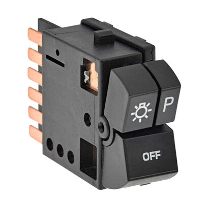
6 terminal headlight switch pinout?
- Thread starter Roblq84
- Start date
You are using an out of date browser. It may not display this or other websites correctly.
You should upgrade or use an alternative browser.
You should upgrade or use an alternative browser.
Never had one of them apart. I have NO idea what the pin out is off the top of my head, but not all the pins are used, IIRC. You would need to look at the connector itself to see which wires go where. I'm going to go out on a limb and say it's similar to Oldsmobile Cutlass lamp switch wiring since it's the same part number. I don't have a Buick book, but the Cutlass one should suffice.
Ok, just looked at the diagram. There should be 4 wires on each side of the switch unit, with dimmer switch on the right, headlamp on the left, but it's been a while since I've looked at one. If you can't see the wires with the switch removed, The connectors can be unclipped from their locations and moved to where you can see the wiring. IIRC, it's a bit tough since they didn't give you much slack but it's do-able. The release clip is on the inboard side of the connector and you have to reach around the back to unclip it, IIRC. PITA. I'm rambling because I haven't had coffee yet, but bear with me.
There's an orange wire in for the power from the taillight fuse, which is the park lamp circuit. A red wire in from hot at all times battery bus.
For outputs, you have a yellow wire to the dimmer switch (headlamp hi beam/lo beam). And a brown wire out for the parking and tail light circuit.
For anyone interested in where to install headlight relays, if you're into that sort of thing, the yellow wire, which is input to the dimmer switch on the column, is where you would likely tap into if you wanted to set up a single relay from battery power to power up the headlamp circuit. If you went dual relays, you would pick the tan (lo beam) and green wires (hi beam) out of the dimmer to install as the relay trigger voltage. But that's another ball of wax.
It's been so long since I've had a headlamp switch out I can't remember which goes where on the connector for absolute sure. If anyone has a car that has their rocker headlamp switch out, look and see the connector wire stack for the headlamp side.
You, or someone, needs to verify this visually if possible, but starting from the top of the switch connector C2, it has A,B,C,D,E,F terminal positions based on the diagram:
A) Brown- out to parking lamp circuit.
B) NOT USED
C ) Red- hot in.
D) Yellow- out to dimmer switch when headlamp switch is on.
E) Orange- in from tail light fuse.
F) NOT USED
You could do a resistance check between terminals:
Between pins A and E to verify the brown and orange. When off, you should see infinite ohms, or OL. When parking lamp switch is on, you should get continuity (ultra low resistance if any).
Do the same thing between pins C and D to verify the red and yellow if you turn the headlamp switch on.
If it passes this test, then the above pinout should be correct. It doesn't verify the wire positions necessarily, but if it completes the circuit, it's probably right.
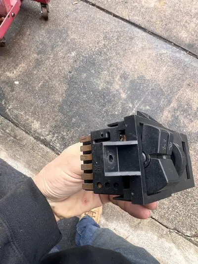
Here's a pic I found of the back of the connector from an 87 Cutlass. Based on how the retaining clip is on the inboard side, then that puts brown at the top, or A terminal.

Here's a diagram of the switch and wiring setup for a Cutlass. Unfortunately it doesn't give specifics on the pin positions, but the above listing should be correct. But again, VERIFY. Don't worry about the 4 wires on the right, as they're for the dimmer switch wheel curcuit as connector C1. The p/n for the lamp switch may be different as it appears the lettering on the OFF button is different from Regal to Cutlass from your diagram (Cutlass has "LIGHTS OFF"), but the switch operates the same.

Ok, just looked at the diagram. There should be 4 wires on each side of the switch unit, with dimmer switch on the right, headlamp on the left, but it's been a while since I've looked at one. If you can't see the wires with the switch removed, The connectors can be unclipped from their locations and moved to where you can see the wiring. IIRC, it's a bit tough since they didn't give you much slack but it's do-able. The release clip is on the inboard side of the connector and you have to reach around the back to unclip it, IIRC. PITA. I'm rambling because I haven't had coffee yet, but bear with me.
There's an orange wire in for the power from the taillight fuse, which is the park lamp circuit. A red wire in from hot at all times battery bus.
For outputs, you have a yellow wire to the dimmer switch (headlamp hi beam/lo beam). And a brown wire out for the parking and tail light circuit.
For anyone interested in where to install headlight relays, if you're into that sort of thing, the yellow wire, which is input to the dimmer switch on the column, is where you would likely tap into if you wanted to set up a single relay from battery power to power up the headlamp circuit. If you went dual relays, you would pick the tan (lo beam) and green wires (hi beam) out of the dimmer to install as the relay trigger voltage. But that's another ball of wax.
It's been so long since I've had a headlamp switch out I can't remember which goes where on the connector for absolute sure. If anyone has a car that has their rocker headlamp switch out, look and see the connector wire stack for the headlamp side.
You, or someone, needs to verify this visually if possible, but starting from the top of the switch connector C2, it has A,B,C,D,E,F terminal positions based on the diagram:
A) Brown- out to parking lamp circuit.
B) NOT USED
C ) Red- hot in.
D) Yellow- out to dimmer switch when headlamp switch is on.
E) Orange- in from tail light fuse.
F) NOT USED
You could do a resistance check between terminals:
Between pins A and E to verify the brown and orange. When off, you should see infinite ohms, or OL. When parking lamp switch is on, you should get continuity (ultra low resistance if any).
Do the same thing between pins C and D to verify the red and yellow if you turn the headlamp switch on.
If it passes this test, then the above pinout should be correct. It doesn't verify the wire positions necessarily, but if it completes the circuit, it's probably right.
Here's a pic I found of the back of the connector from an 87 Cutlass. Based on how the retaining clip is on the inboard side, then that puts brown at the top, or A terminal.
Here's a diagram of the switch and wiring setup for a Cutlass. Unfortunately it doesn't give specifics on the pin positions, but the above listing should be correct. But again, VERIFY. Don't worry about the 4 wires on the right, as they're for the dimmer switch wheel curcuit as connector C1. The p/n for the lamp switch may be different as it appears the lettering on the OFF button is different from Regal to Cutlass from your diagram (Cutlass has "LIGHTS OFF"), but the switch operates the same.

Thank you very much for the detailed reply, im
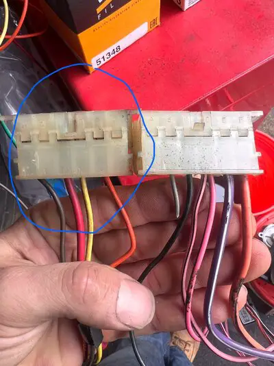
Going to go through the old harness since it’s sitting in a rat nest on my garage floor and I will be sure to post my findings for future reference, the only other picture I found was this one, not sure how accurate, but at least I can somewhat go by wire color, gm was was pretty good about 🤣
I have a standalone front headlight harness that does not use the original half of the square wiring harness from bulkhead to the front, and need to pin them out to the switch myself. The interior dimmer is not going to be used.
Last edited:
Do you know what that switch came out of? That wiring doesn't look like anything I've seen on a G-body.Thank you very much for the detailed reply, im
Going to go through the old harness since it’s sitting in a rat nest on my garage floor and I will be sure to post my findings for future reference, the only other picture I found was this one, not sure how accurate, but at least I can somewhat go by wire color, gm was was pretty good about 🤣
I have a standalone front headlight harness that does not use the original half of the square wiring harness from bulkhead to the front, and need to pin them out to the switch myself. The interior dimmer is not going to be used.
Granted, I'm not 100% sure if every pinout can be used. I just don't know. I'm sure B and F terminals have a reason for being there, but to what they go to and what switch position activates it or not....I dunno.
The B and F terminals are only used if you have the twilight sentinal headlight control thingie. Otherwise, you should have the 4 wires I noted above.
From GNTType.org:

From GNTType.org:
I deleted the previous picture so no one in the future gets confused, I have 2 plugs which are the same connector, from the above posted photo, I’m assuming the headlight switch plug is the one on the left (circled)
I’m going to assume
-brown is parking power
-red is headlight 12v hot/power
-yellow goes to dimmer/high/low beam switch
-orange is tail light 12v hot/power
Does this seem correct?
I’m going to assume
-brown is parking power
-red is headlight 12v hot/power
-yellow goes to dimmer/high/low beam switch
-orange is tail light 12v hot/power
Does this seem correct?
Attachments
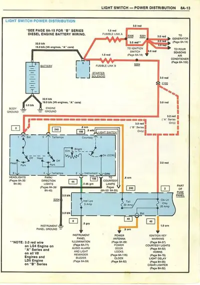
Yep. Red is coming from the battery power harness, specifically Fusible link "B" from the starter solenoid through the big harness connector at the firewall, C100. Coming through the firewall, it splits two ways, one red wire goes to the headlamp switch, the other to the fuseblock for the clk-cig fuse, which also feeds the taillight fuse on the upstream side of the fuse. The orange wire comes from the taillight fuse downstream side to the 5th position on the headlamp switch.
Brown goes to the parking lamps and tails, and the yellow goes to the power the headlamps through the dimmer switch.
Brown goes to the parking lamps and tails, and the yellow goes to the power the headlamps through the dimmer switch.
Yep. Red is coming from the battery power harness, specifically Fusible link "B" from the starter solenoid through the big harness connector at the firewall, C100. Coming through the firewall, it splits two ways, one red wire goes to the headlamp switch, the other to the fuseblock for the clk-cig fuse, which also feeds the taillight fuse on the upstream side of the fuse. The orange wire comes from the taillight fuse downstream side to the 5th position on the headlamp switch.
Brown goes to the parking lamps and tails, and the yellow goes to the power the headlamps through the dimmer switch.
Attachments
So with my aftermarket harness, (colors may not corrospond but are labeled as such)
I have 4 wires,
red main power, red to red 12 v constant
I have light blue which comes from my dimmer switch which goes to yellow
one for rear parking/tail lamps brown to brown
One for front parking lamps which also gets wired together with brown for all 4 corner parking/tail lamps
And I’m just going to jump orange to red to supply the tail lamp power
Everything works like this, do you see any issues running the wires this way? Each wire is fused at the fuse block, and main has the 30 amp silver circuit breaker in the fuse box. it’s a very simplified harness with minimal circuits, it just doesn’t have the extra designated red power wire to the tail lamp, so I’ll jump
It together at the switch
Thanks again!
Last edited:
Similar threads
- Replies
- 12
- Views
- 607
- Replies
- 0
- Views
- 659
- Replies
- 3
- Views
- 2K
- Replies
- 0
- Views
- 788
GBodyForum is a participant in the Amazon Services LLC Associates Program, an affiliate advertising program designed to provide a means for sites to earn advertising fees by advertising and linking to amazon.com. Amazon, the Amazon logo, AmazonSupply, and the AmazonSupply logo are trademarks of Amazon.com, Inc. or its affiliates.